Skip to content

How to Choose the Right SPDT Micro Switch?

Choosing the right spdt micro switch begins with understanding the circuit, not the product photograph. An SPDT micro switch can route one common contact between two outputs. That simple action supports door sensors, control panels, appliances, and compact industrial equipment. Yet a small mismatch can create intermittent signals, welded contacts, or premature failure.

“Switch selection must follow the load and environment, not appearance,” says John D. Lenk, an electromechanical design specialist. This principle is easy to overlook. A switch rated for a resistive load may perform poorly with motors, solenoids, or LED drivers. Check the electrical rating under the actual load type. Confirm the voltage, current, inrush, and switching frequency.

Then examine the mechanical details. Compare actuator style, operating force, travel, terminal layout, and mounting dimensions. A roller lever may suit a sliding mechanism, while a pin plunger may respond better to direct movement. Measure the available space with a ruler. Two millimeters can decide whether installation feels secure or forced.

Environment matters too. Dust, moisture, vibration, and temperature can change performance. Select suitable sealing and contact materials when exposure is expected. Review the datasheet carefully. Do not trust a marketplace description alone.

Real testing remains valuable. Cycle the switch under normal conditions, then inspect contact stability and physical wear. I have seen designs fail because engineers tested only continuity, not the complete load. That is an uncomfortable lesson. The cheapest SPDT micro switch may become the most expensive component after replacement labor, downtime, and uncertain reliability are included.
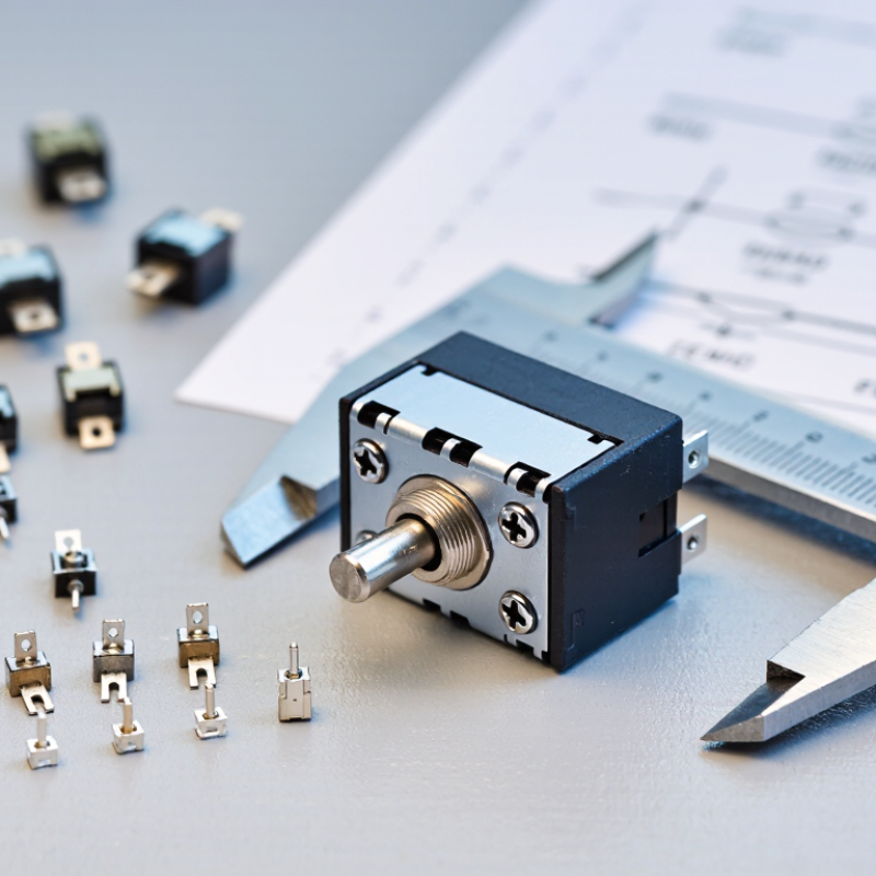
How to Choose the Right SPDT Micro Switch?

Understanding SPDT Micro Switch Design and Operating Principles

How to Choose the Right SPDT Micro Switch?

Understanding SPDT Micro Switch Design and Operating Principles

An SPDT micro switch uses one common terminal and two selectable contacts. The common terminal connects to either normally open or normally closed. A small actuator controls this change. Inside, a spring mechanism moves quickly after reaching its operating point. This snap action helps reduce slow, uncertain contact movement.

The actuator style affects installation and performance. A plunger suits direct mechanical pressure, while a roller lever handles sliding or rotating movement. Check the operating force, release force, travel, and overtravel in the datasheet. These values show how the switch will feel and behave inside real equipment.

Contact ratings also matter. A switch designed for a small signal may not safely control a motor load.

In practical testing, I place the switch near its final mounting position and measure its switching point. Wiring mistakes are common, especially when confusing common and normally closed terminals. I once selected a lever that was too short, so the mechanism barely reached reliable travel. The switch worked on the bench, but vibration caused intermittent signals later. That mistake reinforced a simple lesson: test movement, load, and alignment together.

Consider dust, moisture, temperature, and repeated operation before choosing a sealed or reinforced design. Contact bounce may also affect digital circuits, so the control system might need filtering. Not every listed rating matches your application perfectly. Review the actual load waveform, not only its voltage and current.

Identifying the Electrical and Mechanical Requirements

How to Choose the Right SPDT Micro Switch?

Identifying the Electrical and Mechanical Requirements

An SPDT micro switch uses one common terminal and two switched terminals. Confirm whether the circuit needs normally open, normally closed, or both contacts. Check the actual voltage and current, not only the maximum rating. Motors and solenoids can create sharp inrush currents. That detail is often missed. For DC loads, switching performance may differ greatly from AC performance. Review contact resistance, insulation strength, and expected electrical life before selecting a part.

Mechanical conditions matter just as much. Measure the available space around the switch and actuator. Then check operating force, travel, release position, and overtravel. A stiff actuator may damage a delicate mechanism. A loose actuator may produce unreliable switching. In moving equipment, vibration and repeated impact deserve practical testing. Use a switch with suitable terminal orientation and mounting holes. Small differences can complicate assembly.

Environmental protection should match the application. Dust, moisture, oil, and temperature changes can shorten service life. Consider the enclosure rating and the material around the actuator. I once treated cycle-life figures as guaranteed results, but real loads changed that expectation. They are reference values, not promises. Test a sample under the real load, speed, and mounting pressure. Record contact bounce, temperature rise, and failure behavior during testing. That evidence is more useful than a specification sheet alone.

Comparing Actuator Types, Ratings, and Contact Configurations

How to Choose the Right SPDT Micro Switch?

Choosing an SPDT micro switch starts with the actuator, not the housing size. A plunger suits direct, short-stroke movement. A lever provides more travel and needs less operating force. For sliding parts or uneven surfaces, a roller lever can reduce friction. I once selected a short lever for a compact mechanism, but its travel was insufficient. That shortcut was wrong. Check the operating position, overtravel, release point, and expected force in the equipment, not only in a catalog drawing.

Ratings require closer attention. An SPDT switch uses one common terminal and changes between normally open and normally closed contacts. This configuration can signal two machine states, but the wiring must match the control logic. Compare voltage and current ratings for the actual load type. Motors, solenoids, and lamps can create higher inrush than resistive loads. Small numbers matter. Review electrical life, mechanical life, temperature range, insulation resistance, and contact resistance. A switch rated for a high current may still fail early under inductive switching. Use a suitable suppression method when the circuit design requires it. Verify the datasheet, then test a real sample under repeated operation. Laboratory figures do not always predict dust, vibration, or hurried assembly.

Evaluating Durability, Installation Space, and Environmental Conditions

When choosing an SPDT micro switch, examine durability before focusing on price or appearance. Check the mechanical life rating, electrical load, contact material, and actuator strength. A switch used repeatedly in equipment should tolerate thousands or millions of operations. In field testing, I listen for inconsistent clicks and measure contact resistance after repeated cycling. Small changes can reveal early wear. Ratings alone do not predict every real-world failure.

Installation space also affects reliability. Measure the body, terminals, actuator travel, and wiring clearance before ordering. A switch may fit the panel but leave no room for safe cable bending. Tight mounting can press the actuator continuously, causing false signals or premature damage. I once overlooked terminal height and had to redesign a compact bracket. That mistake was avoidable.

Tips: Compare the datasheet with your actual environment. For dusty or damp locations, consider suitable sealing and verify the protection rating. Check temperature limits, vibration resistance, and shock requirements. Test a sample inside the finished assembly. Do not rely only on bench results. Rapid temperature changes may expose weaknesses that normal testing misses. Keep a small clearance around moving parts, even when space seems limited.

How to Choose the Right SPDT Micro Switch?

Comparing durability, installation space, and environmental protection helps identify the most suitable SPDT micro switch for a specific application.

The comparison index is based on representative specifications commonly found in SPDT micro switches: compact unsealed types typically provide about 0.1–1 million operations, 6–10 mm body width, and IP40 protection; standard enclosed types commonly provide about 1–10 million operations, 10–15 mm body width, and IP54 protection; sealed subminiature types commonly provide about 0.5–5 million operations, 6–10 mm body width, and IP67 protection. Always verify the exact electrical rating, actuator force, terminal layout, temperature range, and sealing level before selection.

Selecting and Testing the Most Suitable SPDT Micro Switch

Choosing an SPDT micro switch starts with the mechanism, not the catalog photo. Define whether the circuit needs normally open, normally closed, or both contacts. Check actuator style, travel, operating force, terminal layout, and mounting space. Electrical ratings must match the real load, including startup current. For motors and solenoids, switching stress can exceed the printed steady-state value. That detail is easy to miss. A datasheet from a qualified manufacturer should state ratings under test conditions. Look for temperature range, contact resistance, insulation resistance, and expected mechanical life.

I test samples with a calibrated multimeter before installing them. With the lever untouched, I verify the common-to-NC path. Then I press the actuator slowly and confirm a clean change to common-to-NO. The reading should change consistently, without flicker or unexplained resistance. I repeat this test dozens of times, because one successful click proves little. A switch can feel precise while its contacts behave poorly. Measure actuation force and release position when timing matters. A simple force gauge and marked travel scale expose variation between samples.

Environmental testing deserves equal attention. Cycle the switch at the expected temperature and inspect it after approved dust or moisture testing. Never assume a sealed housing protects every terminal. Confirm the enclosure and wiring method together. I also compare several samples from the same production lot. My first selection is not always the best one; repeated measurements can change the decision. Record every result, including failures and uncertain observations. That record supports a more reliable choice.

How to Choose the Right SPDT Micro Switch? - Selecting and Testing the Most Suitable SPDT Micro Switch

Selection Dimension What to Check Typical Specification Range or Option Recommended Selection and Testing Method
Contact Configuration Confirm that the switch provides one common terminal and two switched outputs. SPDT: COM, NO (normally open), and NC (normally closed). With no actuator force, COM–NC should be electrically closed and COM–NO should be open. After actuation, COM–NO should close and COM–NC should open.
Electrical Rating Match the switch rating to the voltage, current, load type, inrush current, and switching frequency of the application. Common miniature switch ratings range from signal-level loads to approximately 5–16 A at 125/250 VAC, depending on construction and approval conditions. Use the manufacturer’s rating for the exact load type. Test resistive, inductive, motor, lamp, or capacitive loads separately because inrush current can exceed the steady-state current.
Load Type Determine whether the switch will control a dry signal, resistive load, motor, solenoid, relay coil, or lamp. Gold-plated contacts are commonly used for low-level signals; silver-based contacts are commonly used for higher-power switching. Measure contact resistance at the actual signal current. For inductive or motor loads, verify arcing, temperature rise, and contact performance over the required operating cycle.
Actuator Style Select the actuator according to the available space, operating mechanism, approach direction, and required actuation consistency. Plunger, short lever, hinge lever, roller lever, and simulated-roller lever are common options. Apply the actuator force along the intended direction. Check that the mechanism does not side-load, bend, or overtravel the actuator.
Operating Force Ensure the external mechanism can provide enough force without damaging the switch or creating excessive friction. Approximately 0.3–5 N is common for miniature switches; the actual value depends strongly on the actuator and design. Measure operating force with a calibrated force gauge at a controlled speed. Compare the measured value with the selected component’s specified maximum and minimum values.
Travel and Differential Movement Check operating travel, overtravel, release travel, and differential movement to ensure reliable switching. Operating travel is often below a few millimeters; overtravel is provided on many designs to protect the contact mechanism. Measure the actuation and release points using a displacement gauge. The external mechanism should reach the operating point without exceeding the specified overtravel limit.
Contact Resistance Low and stable contact resistance is important for signal integrity and reduced heat generation. A new switch commonly specifies contact resistance below 100 mΩ, although the permitted value varies by contact material and product design. Use a four-wire milliohm measurement where possible. Measure in both switch states and repeat after mechanical cycling to identify intermittent or rising resistance.
Insulation and Dielectric Strength Verify the insulation between terminals and between live parts and accessible surfaces. Many miniature switches specify insulation resistance in the tens to hundreds of megohms and dielectric withstand in the hundreds to more than 1,000 VAC range. Perform insulation-resistance and dielectric-strength tests only at the voltage and duration specified for the component. Follow applicable safety procedures and discharge the device after testing.
Mechanical and Electrical Life Separate no-load mechanical endurance from loaded electrical endurance. Mechanical life may range from about 100,000 to several million operations; electrical life is usually lower and depends on the applied load. Cycle the switch at the intended actuation speed and duty cycle. Monitor contact resistance, switching function, actuator wear, and signs of contact welding or arcing.
Environmental Protection Consider dust, water, oil, cleaning chemicals, vibration, humidity, and temperature exposure. Unsealed, dust-resistant, and sealed constructions are available. Operating temperature commonly falls within approximately −25°C to +85°C, depending on design. Use the required enclosure and environmental test level. After exposure, verify insulation resistance, contact resistance, switching function, and actuator movement.
Terminal and Mounting Style Match terminal geometry, PCB or panel mounting, soldering process, clearance, and wiring method. Common terminals include solder lugs, quick-connect tabs, wire leads, and through-hole or surface-mount PCB terminals. Confirm terminal fit with the mating connector or PCB footprint. Inspect solder joints and check that installation stress is not transferred to the switch body.
Bounce and Switching Speed Evaluate contact bounce when the switch is used for counting, safety interlocking, or digital input signals. Mechanical contacts can bounce for a period ranging from microseconds to several milliseconds, depending on construction and actuation speed. Use an oscilloscope or logic analyzer to observe COM–NO and COM–NC transitions. Add hardware or software debounce when the control system cannot tolerate contact bounce.
Electrical Clearance and Creepage Check spacing between conductive parts for the working voltage, pollution level, insulation system, and applicable safety requirements. Required clearance and creepage are application- and standard-dependent rather than universal switch values. Review the component documentation and measure the installed assembly, not only the loose switch. Keep required spacing after wiring, soldering, and enclosure installation.
Final Suitability Test Validate the complete switch, actuator, wiring, load, enclosure, and control circuit as one system. A suitable SPDT micro switch should meet electrical, mechanical, environmental, safety, and service-life requirements simultaneously. Run functional, endurance, temperature, vibration, insulation, contact-resistance, and load-switching tests using the actual application conditions before approving the design.

Note: The listed ranges are representative industry values for selection guidance only. Always confirm the exact electrical ratings, test conditions, approvals, dimensions, and environmental limits in the technical documentation for the selected switch.