7 PCB Flex Buying Tips for Global Buyers
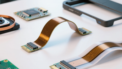
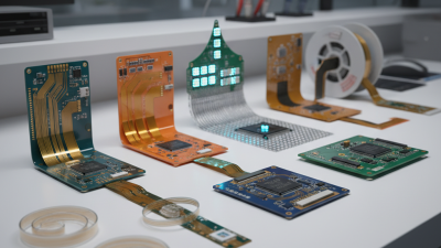
For global buyers, selecting pcb flex is not just a price comparison. The circuit must match the product’s bend pattern, space limits, electrical load, and expected service life. Ask suppliers to confirm layer count, copper type and thickness, coverlay, stiffeners, and minimum bend radius against the design files. These details affect manufacturability and performance. A sample may fold neatly on a desk, then crack after repeated movement in a real device. That risk deserves testing. Request a prototype plan that reflects the final stack-up, connector area, and assembly process, not a simplified substitute. It is easy to overlook.
Compare quotes using the same revision, and include tooling, inspection, packaging, freight, and costs tied to order quantity. Check whether the supplier can provide traceable material information, inspection records, and clear answers about defects or engineering changes. For overseas orders, confirm production lead time, shipping terms, sample approval steps, and who owns each decision. Photos or reports from actual production can help; polished brochures alone prove little. A reliable partner should explain trade-offs plainly, including limitations. Not always. In practice, buyers sometimes accept a cheaper quote before checking how the flex area will be supported during assembly. That can create delays, even when the board meets its drawing. The tips below offer a disciplined way to compare suppliers, verify samples, and manage delivery without treating every promise as proof.
Define Application, Layer Count, and Static or Dynamic Flex Requirements
7 PCB Flex Buying Tips for Global Buyers
Define Application, Layer Count, and Static or Dynamic Flex Requirements
Before requesting a flexible PCB quote, describe how the assembly will be used. Include its location, available space, connector position, and exposure to heat or vibration. A camera module folded once during installation has different needs from a display cable that bends every time a lid opens. State the expected bend area and whether the board moves during operation. Small details matter. A dimensioned sketch or sample movement path can prevent assumptions that are costly to correct later.
Choose the layer count around electrical and mechanical needs, not habit. A simple sensor connection may work with two layers, while controlled impedance or denser routing can require more. Extra layers may increase thickness and make bending less forgiving. Specify copper thickness, coverlay, stiffener locations, and any components near the bend. For static flex, check that the board bends only during assembly and stays supported afterward. For dynamic flex, share the approximate bend radius, movement direction, and expected cycle count. Do not guess. These figures help a fabricator assess the design, though early estimates may need revision after testing. A tight bend drawn neatly in CAD can still fail in a real enclosure. I have seen that requirement treated as a minor detail; it rarely is.
Set Bend-Radius Targets Using IPC-2223 and 6×–10× Thickness Guides
A bend-radius target should start with the finished flex thickness, not the polyimide film alone. IPC-2223 is commonly used as a design reference for flex circuits; its construction-based guidance is often summarized as a minimum radius of roughly 6–10 times thickness for suitable static bends. Treat that range as a screening value, not a guarantee. A 0.20 mm stack, for example, suggests a 1.2–2.0 mm radius. Small? Yes. But adhesive, copper, coverlay, and layer count all affect strain.
Tip:
Put the bend in a uniform area. Keep vias, pads, stiffener edges, and sharp copper corners outside the curved zone. State whether the drawing gives the inside radius or another measurement; ambiguity can shift the actual bend. For repeated motion, do not rely on the static 6×–10× guide. Request a larger radius and test the real stack through the expected movement cycles. IPC-6013 provides qualification and performance requirements, but assembly-specific cycling still matters.
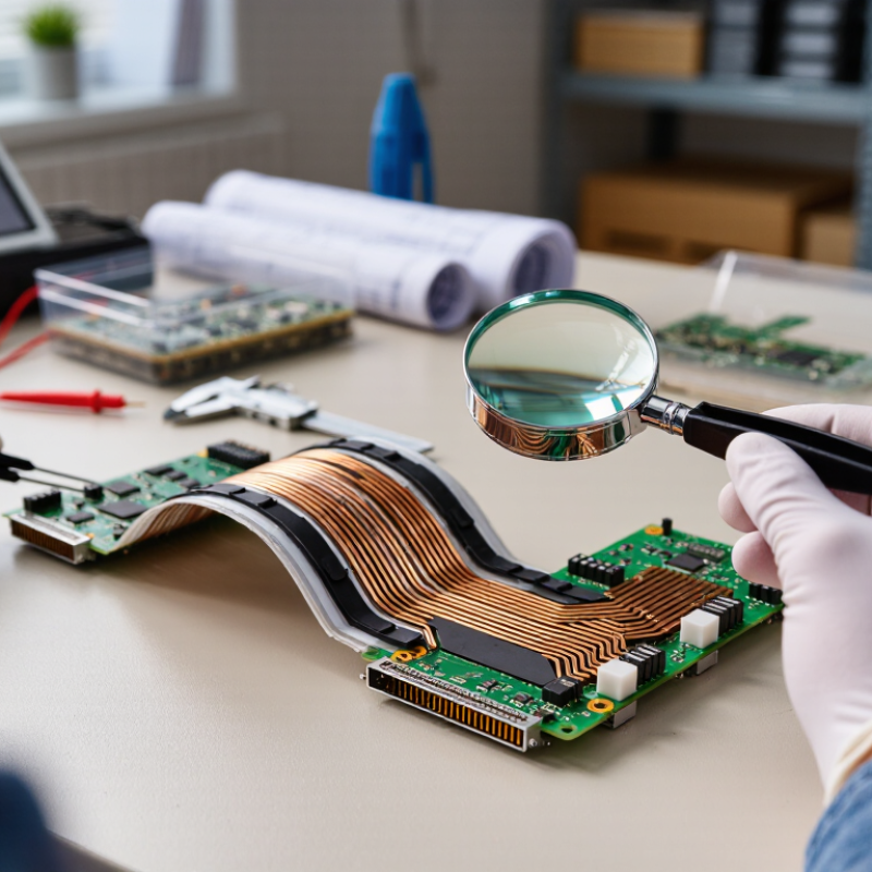
Before release, inspect a bent sample under magnification. Look for whitening, lifted coverlay, or cracked copper near the transition. Record the stack thickness and bend radius used. One imperfect detail can change the result: the assembly may be thicker at the bend than the nominal drawing suggests.
Source references: IPC-2223 flex-circuit design guidance and IPC-6013 qualification requirements.
Compare Copper Weights: 18 µm (½ oz) and 35 µm (1 oz) Are Common
For many flex circuits, 18 µm (½ oz) and 35 µm (1 oz) copper are practical starting points. These figures describe nominal foil thickness, not always the final trace thickness after processing. The thinner option can support finer features and reduce material in a compact stack-up. It may suit signal routing where space and bendability matter. But thinner traces have less copper cross-section, so current, temperature rise, and voltage drop need careful review.
A 35 µm layer offers more conductive material and may help with higher-current paths. It can also require wider traces or more spacing, depending on the design rules and fabrication process. More copper is not automatically safer. Etching can narrow traces, and tight bends can stress conductors. For repeated flexing, ask whether rolled-annealed copper is appropriate; foil type matters alongside thickness.
Compare the supplier’s finished-copper data, trace tolerances, and bend guidance, not just the nominal ounce rating. Check current and thermal calculations against the actual stack-up, then review a prototype under its real bend radius. A static test may miss fatigue in a moving assembly. I have seen thickness chosen early and reconsidered later; it is an easy detail to overlook. Good purchasing notes should state the copper weight, foil type, and whether the circuit bends once or repeatedly.
Copper Weight Comparison for Flexible PCBs
Half-ounce copper is approximately 18 µm thick, while one-ounce copper is approximately 35 µm. Using copper’s density of about 8.96 g/cm³, these thicknesses correspond to roughly 161 and 314 g/m² of copper, respectively. Actual finished thickness may vary with manufacturing and plating.
Qualify Suppliers with IPC-6013, ISO 9001, and Lot-Level Test Records
7 PCB Flex Buying Tips for Global Buyers
IPC-6013, ISO 9001, and Lot-Level Test Records
For flexible circuits, a certificate is only the starting point. IPC-6013 sets qualification and performance requirements for flexible printed boards; specify the applicable revision and product class in your purchase documents. ISO’s Survey 2023 recorded more than 1.2 million valid ISO 9001 certificates worldwide. That scale makes one distinction important: a quality-management certificate does not prove that a particular flex lot passed inspection. Certificates are not proof.
Tip: Request a sample lot package before approval. Check that the records identify the lot, material batch, test date, and acceptance criteria. Look for electrical continuity and isolation results, inspection findings, and any documented rework. Match the results to the drawing revision and agreed IPC-6013 class. A neat summary helps, but ask for underlying test data when a result looks unclear. One gap remains: record formats vary between suppliers, so review them against your own incoming-inspection needs.
Before placing a production order, compare the supplier’s stated controls with actual records from a recent lot. Confirm who approved deviations and how affected boards were contained. ISO 9001:2015 supports controlled production and traceability where required, but buyers still need to define what evidence they expect. Keep the checklist practical: one board lot, one drawing revision, and traceable results you can verify.
Verify RoHS Compliance: Lead Is Limited to 0.1% per Homogeneous Material
When buying a flexible PCB, ask how the supplier verifies RoHS lead limits. The maximum is 0.1% by weight, or 1,000 parts per million, in each homogeneous material. This is not a limit averaged across the complete circuit. Copper, polyimide, coverlay adhesive, solder, and surface finishes may need separate evaluation. Looks can mislead.
Request material declarations and test evidence that identify the relevant components and production lot. A report for the base film alone does not confirm the adhesive or finish.
In practice, unclear material names can make a technically sound report hard to connect to the board you are ordering. Ask for traceability from the tested sample to the finished flex circuit, and check that document dates match the current material specification.
For complex builds, confirm who is responsible for collecting evidence from material suppliers and how changes are reviewed. A substitute adhesive or plating process may affect compliance, even when the board outline stays unchanged. Do not treat a certificate as a permanent guarantee. Keep the records. Also ask whether any declared exemption applies, and verify its scope and validity for your specific product before approving the purchase.