Skip to content

2026 Top Types of Printed Circuits for Global Buyers

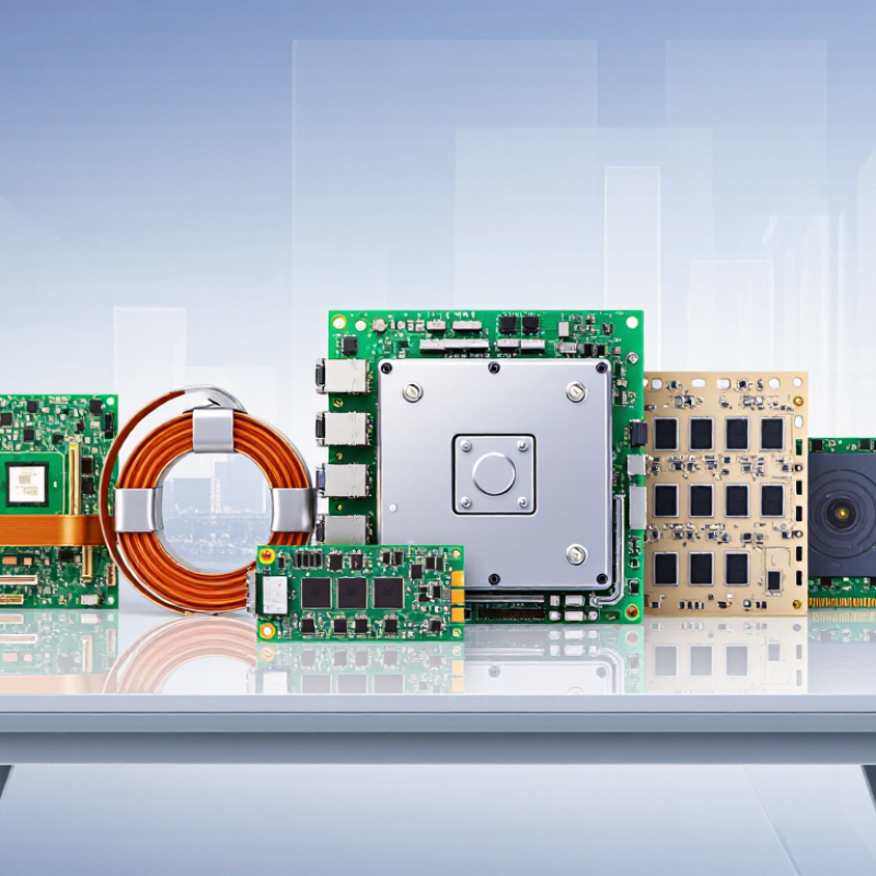
In 2026, global buyers will face a wider choice of printed circuits than ever before. Each type answers a different engineering problem. Rigid PCBs support stable, cost-efficient designs. Flexible circuits bend around hinges, cameras, and compact medical devices. Rigid-flex boards combine both advantages, but their qualification process can be demanding. HDI boards reduce space through microvias and fine-line routing. Metal-core circuits manage heat beneath high-power LEDs and automotive modules. RF and microwave boards serve wireless equipment, radar systems, and satellite communication.

Dr. Paul Eisler, widely recognized as a pioneer of printed circuit technology, wrote, “The printed circuit is a method of wiring electrical circuits.” His observation still matters. A board is not simply a flat green plate. Copper thickness, dielectric performance, thermal paths, surface finish, and assembly capability can determine whether a product survives real use. Buyers should examine supplier experience, test records, material traceability, and production consistency. A low quotation may hide higher rework costs.

There is no universal best type. That is the uncomfortable part. A flexible circuit may solve packaging problems but introduce bending-life concerns. HDI can save valuable space, yet it requires tighter process control. Ceramic substrates offer excellent thermal performance, but their cost and availability may limit adoption. This guide compares the top printed circuits for global purchasing decisions in 2026. It considers performance, reliability, manufacturing complexity, delivery risk, and total ownership cost. Specifications still need careful review. Even experienced teams can miss one critical detail.
2026 Top Types of Printed Circuits for Global Buyers

Printed Circuit Basics and Their Role in Modern Electronics

Printed circuits are the physical nervous system of modern electronics. They connect components through copper traces, pads, vias, and insulating layers. A rigid board suits computers and industrial controls, while flexible circuits bend inside cameras, medical sensors, and compact displays. Rigid-flex boards combine both advantages, but their manufacturing demands tighter mechanical control.

Signal speed changes the design rules. High-density interconnect boards use microvias and finer traces to save space. Multilayer boards separate power, ground, and high-speed signals across controlled structures. Metal-core boards move heat from power components into a thermal backing. The choice is never only about price. I have seen small layout decisions create difficult assembly and repair problems later.

The 2025 WSTS Spring Market Forecast values global semiconductor sales at 697 billion US dollars for 2025, an 11.2% annual increase. That growth raises demand for reliable printed circuit assemblies across data, automotive, and consumer systems. IPC’s 2024 Technology Roadmap also emphasizes higher density, thermal management, and stronger material performance. These priorities matter to global buyers comparing suppliers. A cheaper board may fail earlier under heat, vibration, or repeated bending. That risk is easy to underestimate. Designers should verify layer construction, copper thickness, impedance data, testing coverage, and applicable compliance records before approval. Forecasts can change, and specifications sometimes look precise while hiding weak assumptions.

2026 Top Types of Printed Circuits for Global Buyers

Printed circuit basics and their role in modern electronics

The chart compares representative common copper-layer counts across major printed circuit types. Single-sided and double-sided boards support simpler electronics, while multilayer, HDI, flexible, and rigid-flex circuits provide higher routing density or mechanical flexibility for advanced products.

Main Types of Printed Circuits Available to Global Buyers

Global buyers can choose several main types of printed circuits, depending on space, heat, cost, and assembly volume. Single-sided boards suit simple controls and low-cost products. Double-sided boards provide more routing capacity without a major price increase. Multilayer PCBs support dense computing, industrial equipment, and communication systems. They usually offer better signal control, but require tighter fabrication management.

Flexible circuits bend around hinges, cameras, and compact medical devices. Rigid-flex boards combine stable sections with bendable connections, reducing cable count and assembly points. Metal-core PCBs use aluminum or copper bases to move heat away from LEDs and power components. High-density interconnect boards use microvias and fine traces for smaller devices. The boundary is not always clean. Some buyers call advanced multilayer boards HDI, although the design may not fully meet IPC definitions.

Prismark’s 2024 industry forecast placed global PCB sales near US$75 billion in 2023 and expected continued growth through 2028. This growth reflects stronger demand for high-layer-count, flexible, and high-frequency designs. Still, buyers should not select the most advanced type automatically. IPC-2221 and IPC-6012 provide useful design and qualification references, but factory capability matters just as much. In production reviews, a low-cost double-sided board can outperform a costly multilayer design when routing and heat requirements remain modest. That decision is easy to underestimate. Suppliers should confirm copper thickness, dielectric material, impedance tolerance, bend radius, surface finish, and test coverage before approving samples. Looking only at unit price often creates expensive revisions later.

How Printed Circuit Types Differ in Design, Materials, and Performance

Printed circuits differ most clearly in their layer structure, base materials, and intended working conditions. Single-sided boards suit simple controls and low-density layouts. Double-sided boards support more routing, but require careful through-hole planning. Multilayer boards fit compact equipment with dense connections and controlled signal paths. Rigid-flex circuits reduce connectors and move reliably through repeated bending. The choice is rarely only about price.

Common materials include FR-4 for general electronics, polyimide for flexible sections, and metal-core laminates for heat-heavy applications. Copper thickness affects current capacity and mechanical strength. Dielectric thickness influences impedance, spacing, and signal loss. High-frequency designs may need low-loss materials rather than standard laminates. Small details matter.

Performance depends on more than the board type. Thermal expansion can stress solder joints during temperature changes. Poor stack-up planning may create noise, even when routing looks clean. A thicker copper layer does not automatically improve every design. It can also increase etching difficulty and production variation. The compromise is real.

In practical sourcing, buyers should request layer drawings, material specifications, tolerance data, and test records. Ask how the supplier verifies insulation, surface finish, drilling accuracy, and thermal reliability. Production capability should match the circuit’s complexity, not merely its advertised capacity. I have seen efficient-looking layouts require expensive revisions after assembly. That experience encourages earlier design reviews. A board that passes electrical testing may still fail after vibration, moisture, or repeated heating. Performance claims need conditions, measurements, and traceable documentation.

2026 Top Types of Printed Circuits for Global Buyers - How Printed Circuit Types Differ in Design, Materials, and Performance

Printed Circuit Type Typical Layer Structure Common Base Materials Typical Thickness Design Characteristics Performance Profile Typical Applications Main Advantages Main Limitations
Single-Sided PCB One copper layer on one side of the insulating substrate FR-4, paper phenolic, or composite substrate Commonly about 0.8–1.6 mm No plated through-holes required for basic layouts; components are normally mounted on one side Low design density and limited routing capability; suitable for low-complexity circuits Simple controls, LED lighting, power supplies, calculators, and household products Lowest manufacturing cost; simple fabrication; short production lead time Limited routing area; unsuitable for dense, high-speed, or highly integrated designs
Double-Sided PCB Copper layers on both sides, connected by plated through-holes or vias FR-4 is the most common; high-temperature laminates are also available Commonly about 0.8–2.0 mm Two routing surfaces support greater circuit density and improved component placement Better electrical connectivity and routing flexibility than single-sided boards Industrial controls, automotive modules, instrumentation, and consumer electronics Good balance of cost, density, manufacturability, and mechanical strength Less compact than multilayer or HDI designs; requires more complex drilling and plating
Multilayer Rigid PCB Three or more copper layers separated by dielectric laminates and bonded into one board FR-4, low-loss epoxy laminates, and high-temperature laminate systems Commonly about 1.0–3.2 mm, depending on layer count Dedicated signal, power, and ground planes; controlled impedance can be designed into the stack-up High routing density, improved power distribution, and better electromagnetic compatibility when properly designed Computing equipment, networking hardware, industrial systems, medical electronics, and automotive electronics Compact integration; supports complex circuits, high pin counts, and high-speed signal routing Higher cost; longer fabrication cycle; stack-up, lamination, and testing require tighter process control
Flexible PCB Single-sided, double-sided, or multilayer conductive patterns on a bendable film Polyimide film with rolled or electrodeposited copper; coverlay used for insulation Base film is often about 0.05–0.20 mm before stiffeners and components Designed for controlled bending, folding, dynamic movement, or three-dimensional packaging Lightweight and vibration-tolerant; dynamic-bend life depends on bend radius, copper type, and construction Displays, cameras, wearables, medical instruments, automotive interiors, and compact electronic assemblies Reduces wiring, weight, connectors, and assembly volume; fits irregular spaces Higher material and assembly cost; requires careful handling and bend-radius control
Rigid-Flex PCB Rigid board sections connected by integrated flexible circuit sections FR-4 rigid sections combined with polyimide flexible layers and copper Rigid zones commonly about 0.8–2.4 mm; flex zones are substantially thinner Combines fixed component-support areas with bendable interconnects in one integrated construction High mechanical reliability when the flex transition, bend radius, and reinforcement are correctly designed Aerospace systems, medical devices, compact instruments, cameras, and rugged electronics Reduces connectors and cable assemblies; saves space and improves resistance to vibration High design and manufacturing complexity; repairs and revisions can be more difficult
HDI PCB High-density multilayer construction using microvias, fine lines, and fine-pitch features High-quality FR-4 or low-loss laminates; sequential-build dielectric materials are common Often about 0.6–2.0 mm, depending on the build-up structure Microvias, blind or buried vias, fine-pitch pads, and sequential lamination increase routing density Supports compact high-speed designs and high component counts; requires precise impedance and signal-integrity control Smartphones, compact computing devices, advanced automotive modules, medical electronics, and wearable products More functionality in a smaller footprint; short interconnects can improve signal performance Higher tooling and process costs; yield depends strongly on registration, drilling, plating, and inspection
Metal-Core PCB Copper circuit layer separated from an aluminum or copper metal base by a dielectric layer Aluminum, copper, or copper-aluminum base with thermally conductive dielectric Commonly about 1.0–3.2 mm overall Thermal paths are built into the board structure; usually uses one or two conductive layers Improves heat spreading and reduces thermal resistance compared with standard FR-4 in suitable designs LED lighting, power converters, motor drives, automotive lighting, and heat-generating power electronics Good thermal management, mechanical rigidity, and potential for longer component life Limited routing density; heavier than flexible or standard laminate boards; metal processing affects cost
Ceramic PCB Conductive patterns formed on or within a ceramic substrate, commonly using thick-film or thin-film processes Alumina, aluminum nitride, or other engineered ceramic substrates Commonly about 0.25–2.0 mm, depending on substrate and construction Rigid, dimensionally stable substrate with high-temperature and high-frequency design options Excellent thermal stability, low moisture absorption, and strong performance in demanding environments High-power modules, RF and microwave systems, sensors, automotive power electronics, and aerospace equipment High thermal conductivity options and stable electrical performance at elevated temperatures Brittle compared with laminate boards; machining and processing costs are generally higher
RF and Microwave PCB Single-layer or multilayer controlled-impedance structure with carefully defined transmission lines Low-loss PTFE-based, hydrocarbon-ceramic, or other high-frequency laminate systems Often about 0.5–3.2 mm, selected according to frequency and stack-up requirements Controlled dielectric constant, low dissipation factor, precise trace geometry, and optimized grounding Low signal loss and stable impedance at high frequencies when materials and fabrication are tightly controlled Radar, wireless infrastructure, satellite communications, antennas, test equipment, and navigation systems Supports high-frequency transmission with reduced dielectric and conductor losses Specialized materials and fabrication increase cost; design tolerances and surface quality are critical

Note: Thickness, layer count, materials, electrical performance, and application suitability vary by stack-up, design rules, operating environment, and manufacturing specifications. The ranges shown are typical industry-level reference values rather than universal limits.

Key Selection Factors for International Purchasing Decisions

When international buyers compare printed circuit types, the board’s working environment should guide the decision. Rigid boards suit stable equipment with fixed geometry. Flexible circuits reduce wiring space in moving assemblies. Rigid-flex designs can simplify connections, but their bending zones require careful engineering. High-density boards support compact products, while metal-core versions help move heat away from power components.

Material selection deserves practical attention. Buyers should confirm copper thickness, layer count, dielectric performance, surface finish, and controlled impedance requirements. A small mismatch can affect signal quality or assembly yield. Ask for test reports, material traceability, and sample approval before placing a large order. Small errors matter.

International purchasing also depends on production consistency. Review the supplier’s process controls, inspection equipment, engineering response time, and ability to repeat the same specifications. Clarify minimum order quantities, tooling charges, packaging, shipping terms, and realistic lead times. A low unit price may hide expensive setup work or unreliable delivery. That assumption can fail.

Environmental conditions should remain visible during negotiations. Consider humidity, vibration, temperature cycling, chemical exposure, and expected service life. Request drawings with revision control, not only informal messages. My experience suggests that buyers often focus on price too early. A better comparison includes total landed cost, field risk, repair difficulty, and documentation quality. Even then, the first specification may need revision after prototype testing.

Global Standards, Applications, and Supply Chain Considerations

Printed circuit selection now depends on standards, application stress, and supply resilience. Prismark’s 2024 PCB industry report estimates global PCB sales at roughly US$85 billion. Rigid multilayer boards remain common in computing and industrial controls. HDI supports compact electronics, while flex circuits manage repeated bending in vehicles, medical devices, and wearable equipment. Heavy copper handles higher current, but it increases weight, cost, and thermal design pressure.

Standards must match the board’s real use, not merely its drawing. IPC-6012 covers rigid board qualification, while IPC-2221 guides general design practices. IPC-A-600 defines visible workmanship requirements. For safety-critical products, buyers should request electrical, flammability, and traceability records. ISO 9001 certification helps, but it does not prove every batch is reliable. That distinction is often missed.

Supply-chain reviews should examine copper foil, resin systems, laminates, and regional capacity. UNCTAD’s Review of Maritime Transport 2024 states that over 80% of world trade by volume moves by sea. That makes port disruption a circuit-board issue. Dual sourcing, three-month forecasts, and approved material alternatives reduce exposure. Still, forecasts can fail. A second supplier may share the same upstream laminate source, creating false security. Buyers should audit capacity, change-control discipline, and sample consistency before volume orders.