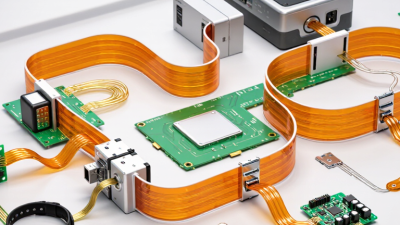
Choosing the right rigid flex pcb supplier can shape product reliability, sourcing stability, and long-term manufacturing costs. This technology combines rigid board strength with flexible circuit movement. It can reduce connectors, wiring space, and assembly steps in compact devices. That sounds simple. It rarely is.
Global sourcing requires more than comparing unit prices. Experienced buyers review material quality, layer structure, bend radius, copper thickness, and controlled impedance requirements. They also examine factory capabilities, process controls, inspection records, and communication practices. A reliable supplier should provide clear engineering feedback before production begins. Design-for-manufacturing reviews can reveal weak vias, sharp flex transitions, or unrealistic bending conditions. These details matter when a circuit moves inside a medical instrument, camera module, or industrial controller.
Supplier verification also deserves careful attention. Request current certifications, traceability records, test reports, and representative samples. Ask how the factory manages material substitutions and engineering changes. A responsive supplier should explain risks rather than promise everything. That honesty is valuable. Yet, no sourcing plan is perfect. Sample performance may not fully predict high-volume consistency, especially across different production batches. Buyers should therefore combine audits, pilot runs, electrical testing, and documented acceptance criteria. Cost savings alone can hide quality risks. A balanced evaluation considers reliability, logistics, technical support, and total ownership cost. With disciplined qualification, rigid flex pcb sourcing can support smaller designs, steadier production, and stronger global supply relationships. The decision still requires judgment.
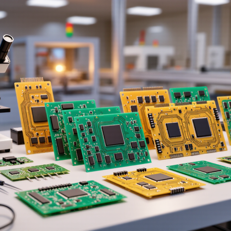
Why Choose Rigid Flex PCB for Global Sourcing?
Rigid-flex PCB construction combines rigid board sections with flexible polyimide layers. This structure supports compact assemblies and repeated bending. It also reduces connectors, wires, and manual assembly points.
A typical design includes copper traces, polyimide dielectric films, adhesive layers, stiffeners, and rigid laminates. The flexible zone manages movement. The rigid zone supports components, connectors, and mechanical mounting. IPC-2223 provides design guidance for flexible and rigid-flex circuits, including bend requirements and material selection. These details matter during global sourcing because poor bend control can create hidden copper fatigue.
The numbers support careful consideration. A 2024 Research and Markets forecast expects the global flexible PCB sector to grow at a double-digit compound annual rate through the decade. Separate industry analyses also identify consumer electronics, medical equipment, and transportation systems as major demand areas. Rigid-flex boards can reduce assembly space and interconnect count, but savings are not automatic. A more complex layer stack may increase fabrication cost.
From practical design reviews, the weakest point is often the transition between rigid and flexible zones. It needs controlled curvature, proper coverlay clearance, and strain relief. A tidy CAD model can still fail during bending tests. That assumption deserves review. Manufacturing drawings should specify bend radius, copper thickness, stiffener placement, and inspection criteria. IPC standards help, but supplier capability and process records remain equally important.
Rigid-flex PCB design starts with mechanical constraints, not just circuit density. Engineers first map the folding path, bend radius, connector position, and enclosure space. Keep bend areas clear. Copper patterns should cross these zones smoothly, without sharp corners or crowded vias. A controlled layer stackup then balances signal integrity, flexibility, and thickness. Rigid sections may carry connectors and components, while flexible sections route signals through moving or narrow spaces.
Manufacturing begins with material selection and a detailed fabrication drawing. Polyimide layers, copper thickness, coverlay, adhesives, and rigid stiffeners all affect reliability. During lamination, heat and pressure must remain consistent across different materials. Small shifts matter. Drilling, laser microvia formation, plating, and etching require careful registration. Experienced manufacturers inspect alignment between rigid and flexible regions before final assembly. Global sourcing also benefits from clear impedance targets, bend specifications, tolerance tables, and material traceability.
Quality checks usually include automated optical inspection, electrical testing, and sample cross-sections. Flex areas may receive repeated bending tests that imitate installation or service movement. I have seen clean prototypes reveal weak transitions near stiffeners after repeated cycling. That failure was not dramatic, but it exposed an overlooked stress point. Design reviews should therefore examine manufacturability, not only the schematic and layout. A practical supplier conversation can uncover risks involving tooling, yield, inspection access, or shipment protection before volume production begins.
| Design and Sourcing Dimension | Typical Technical Guidance | Manufacturing Relevance | Global Sourcing Checkpoint |
|---|---|---|---|
| Construction | Combines rigid laminate sections with one or more flexible polyimide sections in a single interconnected circuit. | The design must define rigid zones, flex zones, coverlay areas, stiffeners, bend regions, and layer transitions before fabrication. | Confirm that the supplier can manufacture the complete rigid-flex stack-up rather than assembling separate rigid and flexible boards. |
| Space and Assembly Reduction | Rigid-flex construction can replace some board-to-board connectors, cables, and wire harnesses. | Fewer interconnects may reduce assembly operations, connector interfaces, and potential contact failures. | Compare total installed cost, including connectors, cable assembly, labor, inspection, and logistics—not only bare-board pricing. |
| Flexible Material | Polyimide is widely used because it provides flexibility, dimensional stability, and relatively high temperature resistance. | Material selection affects bend life, dielectric performance, thermal behavior, thickness, and lamination compatibility. | Request material specifications, applicable compliance declarations, and lot traceability for each production order. |
| Rigid Material | Rigid areas commonly use glass-reinforced epoxy laminate, such as FR-4, when compatible with the electrical and thermal requirements. | Rigid sections provide component-supporting surfaces and stable mounting areas while the flexible sections route signals through moving or folded regions. | Verify laminate grade, glass-transition temperature, copper weight, finished thickness, and controlled-impedance capability. |
| Bend Radius | A common preliminary guideline is a minimum bend radius of about 6 times the finished flexible-section thickness for dynamic applications; the actual value depends on construction and bend type. | Tight bends, sharp corners, unsupported transitions, and copper concentration can increase mechanical stress and reduce flex life. | Have the supplier review the bend model, bend direction, bend radius, number of cycles, and whether the application is static or dynamic. |
| Copper Pattern in Flex Areas | Staggered traces, rounded corners, balanced copper distribution, and avoidance of abrupt width changes are commonly used to improve flex reliability. | Trace geometry must support both electrical performance and repeated mechanical movement. | Check the supplier’s design rules for minimum trace width, spacing, copper thickness, via placement, and dynamic-flex experience. |
| Stiffeners and Coverlay | Stiffeners reinforce connector or component areas, while coverlay protects exposed conductors in flexible regions. | Incorrect stiffener thickness or coverlay registration can affect assembly fit, bend behavior, and exposed-pad dimensions. | Specify stiffener material, thickness, adhesive system, coverlay openings, tolerances, and inspection requirements on the fabrication drawing. |
| Layer Stack-Up | The stack-up should identify rigid-layer build, flex-layer build, copper weights, dielectric thicknesses, coverlay, stiffeners, and plated through-hole structures. | Stack-up control is essential for impedance, registration, total thickness, controlled bending, and lamination yield. | Require a pre-production stack-up approval, impedance calculation where applicable, and documented changes before mass production. |
| Fabrication Sequence | Typical operations include material preparation, imaging, etching, drilling or laser processing, plating, lamination, coverlay application, stiffener attachment, profiling, and testing. | Rigid-flex boards require coordinated processing because rigid and flexible materials respond differently to heat, pressure, moisture, and mechanical handling. | Ask for the process flow, key process controls, first-article records, and evidence of capability for the required layer count and geometry. |
| Plated Holes and Vias | Through vias, blind vias, buried vias, and microvias may be used depending on density, layer count, and manufacturing capability. | Via location and construction should avoid unnecessary stress in active bend zones unless specifically designed and qualified for that use. | Confirm drill tolerance, hole-wall quality, copper plating requirements, via reliability testing, and the supplier’s aspect-ratio limits. |
| Electrical Testing | Bare-board electrical tests commonly include opens-and-shorts testing; flying-probe or fixture-based methods may be selected according to volume and design. | Testing verifies net connectivity but does not replace mechanical, dimensional, material, or visual inspection. | Define test coverage, netlist requirements, test-report format, sampling rules, and responsibility for test fixtures. |
| Quality and Acceptance | IPC-6013 covers qualification and performance specifications for flexible and rigid-flex printed boards; IPC-A-600 provides visual acceptability guidance. | Clear acceptance criteria help control plating, solder mask, coverlay, conductor geometry, delamination, registration, and surface-finish defects. | State the applicable IPC class, revision, inspection method, defect limits, certificate requirements, and corrective-action process in the purchase documentation. |
| Surface Finish | Common finishes include electroless nickel immersion gold, immersion tin, immersion silver, and hot-air solder leveling, subject to design and assembly requirements. | The finish influences solderability, contact performance, shelf life, cost, and compatibility with fine-pitch assembly. | Confirm finish type, thickness range, storage conditions, RoHS or other regulatory requirements, and compatibility with the assembly process. |
| Thermal and Environmental Reliability | Temperature cycling, humidity exposure, soldering heat, vibration, and repeated bending should be evaluated according to the product environment. | Rigid-flex reliability depends on material compatibility, copper adhesion, plated-hole integrity, bend design, and assembly conditions. | Request a qualification plan based on actual use conditions rather than relying only on a generic material datasheet. |
| Documentation Package | A complete package normally includes Gerber or ODB++ data, drill files, stack-up, fabrication drawing, assembly notes, bend details, and controlled revisions. | Complete documentation reduces quotation ambiguity, engineering changes, and interpretation differences between design and production teams. | Use revision-controlled files, formal engineering-change approval, and a written list of deviations from the approved design. |
| Lead Time and Logistics | Rigid-flex lead time is influenced by layer count, material availability, tooling, surface finish, testing, qualification, and order quantity. | Additional lamination and inspection requirements can make rigid-flex production more schedule-sensitive than standard rigid boards. | Separate prototype, qualification, and production lead times; confirm shipping terms, packaging, moisture protection, and continuity planning. |
| Total Cost of Ownership | The bare-board price should be evaluated together with assembly labor, connectors, cable preparation, inspection, field service, and inventory costs. | Integration may reduce part count and assembly complexity, although rigid-flex fabrication itself can require specialized materials and processes. | Compare landed cost, yield assumptions, warranty exposure, minimum order quantities, tooling charges, and expected annual demand. |
Rigid-flex PCBs can simplify global sourcing by combining multiple rigid boards with flexible interconnects. That reduces connectors, cables, assembly steps, and potential failure points. In factory audits, engineers often find value in cleaner routing around hinges, sensors, and compact enclosures. The result is a smaller shipment with fewer individual parts. Less handling matters.
Prismark’s 2024 PCB industry forecast valued the global PCB market at nearly US$70 billion in 2023. Its outlook also points to continued demand from high-density electronics and advanced packaging. A rigid-flex design can support this trend while reducing assembly variation between suppliers.
It also helps standardize inspection, impedance testing, bend-radius checks, and traceability across regions. IPC technical standards provide widely recognized guidance for qualification and reliability testing.
However, rigid-flex is not always the cheapest option. Tooling, material selection, and early design reviews can increase the initial cost. Poor bend control can create expensive field failures. That risk is easy to underestimate.
Global buyers should compare total landed cost, not only the quoted board price. They should request cross-section reports, thermal-cycle data, supplier process limits, and sample builds before mass production. This approach is slower at the beginning, but often more reliable across international supply chains.
Quality, Compliance, and Supply Chain Considerations
Rigid flex PCB sourcing demands more than a competitive quotation. The design combines rigid areas, flexible layers, adhesives, and plated transitions. Each material affects bending life, heat resistance, and assembly yield. Request cross-section drawings, impedance data, and documented inspection results. Small details matter. Check pad geometry near bend zones. Confirm that coverlay openings match the assembly process. A production sample should survive repeated flexing without exposed copper or cracked plating.
Compliance evidence must follow the shipment, not arrive later. Ask for material declarations, restricted-substance test reports, and revision-controlled specifications. Verify whether the supplier can support the destination market’s requirements. Traceability should connect laminate lots, operators, inspection records, and final units. This is especially important for medical, automotive, and industrial equipment. Do not accept vague claims such as “fully compliant.” Evidence is stronger than promises.
Supply continuity also deserves practical testing. Review alternate materials, approved process substitutes, and second-source capabilities before release. A supplier may promise stable capacity, yet struggle when one adhesive becomes unavailable. Ask about humidity-controlled storage, lead-time buffers, and export documentation. Quality audits should include the factory floor, not only a polished presentation. No checklist is perfect. A rushed qualification can miss connector stress or packaging damage. It is worth challenging assumptions, even when the first samples look excellent.
Rigid-flex PCBs suit products where space, vibration, and assembly reliability matter. They combine rigid support areas with flexible interconnects, reducing connectors and wiring. Typical applications include medical monitors, automotive cameras, aerospace controls, wearables, and compact battery systems.
Mordor Intelligence estimates the global flexible electronics market will grow at over 10% annually through 2029. This growth reflects demand for lighter, smaller electronic assemblies.
Selection should begin with the application, not the supplier. Define whether the flex section moves repeatedly or bends only during assembly. Specify bend radius, cycle life, copper thickness, layer count, impedance, and operating temperature.
For high-speed designs, review dielectric stability and controlled-impedance test data. For medical or aerospace products, request traceability, process records, and relevant qualification evidence.
IPC-2223 provides design guidance for flexible and rigid-flex circuits, but real products often need additional testing.
Ask for stack-up drawings, material certificates, cross-section reports, and first-article inspection results. Confirm panelization, tooling ownership, lead times, and repair controls.
The 2024 Global Rigid-Flex PCB Market analysis by Data Bridge Market Research forecasts double-digit market growth during the next decade. Yet market expansion does not guarantee consistent quality.
A supplier may meet electrical specifications while missing dynamic-flex performance. That assumption can fail. Prototype testing should include thermal cycling, vibration, repeated bending, and connector strain.
A perfect checklist does not exist. Product-specific evidence matters more.